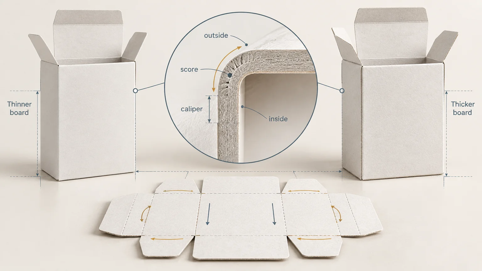
Panel Compensation in Folding Cartons: Why Equal Numbers Do Not Always Fold Equal
TLDR: Folding carton panel compensation adjusts structural geometry for the space consumed and created when paperboard bends. Do not add one board thickness to every panel. First establish whether the critical dimensions are internal, external, or manufacturing dimensions. Then use the converter’s board-specific caliper, inside-loss, outside-gain, crease, and joint settings. Approve the result with a carton made from the intended production stock.
Two panels can have equal score-to-score dimensions on a flat dieline and still fail to produce equal usable spaces after folding. The reason is physical: paperboard has thickness, and a crease turns that thickness through a corner rather than reducing it to a dimensionless hinge. Folding carton panel compensation accounts for that behavior.
The practical answer is to design from the required finished measurement, not from a convenient flat-panel number. A carton protecting a close-fitting product is usually driven by internal clearance. A carton entering a tray, shipper, or shelf fixture may be constrained by its external footprint. The dieline must translate that requirement into score positions that work with the selected board and converting process.
What folding carton panel compensation means
Panel compensation is useful plain-language shorthand for caliper-aware adjustment of a carton’s panels, scores, closures, and joints. It is not a single standardized correction that can be applied identically to every carton.
Several dimensions must be kept separate:
- Caliper is the measured thickness of the paperboard. ISO 534 covers the determination of paper and board thickness, density, and specific volume; its scope excludes corrugated fibreboard, so corrugated structures should not be treated as equivalent here. ISO 534’s paper and board thickness standard
- Inside dimensions describe the clear space available for the product after the carton is erected.
- Outside dimensions describe the carton’s external envelope, including the board surrounding its internal space.
- Score-to-score dimensions locate crease centerlines or other structural references on the flat blank. They are manufacturing dimensions, not automatically the finished inside or outside dimensions.
- Inside loss, commonly abbreviated IL, describes a mechanical-design allowance associated with the inside of a fold.
- Outside gain, or OG, describes the corresponding effect on the outside geometry of that fold.
- Artwork rollover is a graphic allowance near a crease. It helps color or imagery continue across a folded edge, but it does not correct the carton’s structural dimensions.
Packaging CAD systems may store caliper, inside loss, and outside gain as separate board properties. Esko’s ArtiosCAD documentation, for example, identifies all three as distinct variables and describes values near half the caliper as a general starting convention for inside loss and outside gain. That is a modeling starting point, not a universal production setting.
Choose the measurement basis before moving a score
A request to “make the panel 50 mm” is incomplete. It could mean 50 mm of internal clearance, a 50 mm outside footprint, or 50 mm between crease references in the flat blank. Those targets do not necessarily produce the same score positions.
| Measurement basis | Use it when | Main production question |
|---|---|---|
| Internal dimensions | The product must fit with controlled clearance | What usable space remains after the board folds inward? |
| External dimensions | The carton must fit a tray, shipper, fixture, or shelf plan | How much space does the erected board occupy outside the cavity? |
| Score-to-score dimensions | The converter is specifying or checking the flat blank | Which crease references must be manufactured on the sheet? |
| Artwork references | Graphics must align across panels and folded edges | Where will the visible bend and rollover zone occur? |
Record the controlling basis on the drawing or specification. If both inside and outside dimensions matter, identify which values are critical and where they are measured. A vague overall measurement taken across a bowed panel is less useful than a datum between defined surfaces or edges.
Caliper, inside loss, and outside gain are related but not interchangeable
It is tempting to treat a fold as a simple arithmetic problem: add half the board thickness on one side, half on the other, and assume the two allowances equal the measured caliper. That may be acceptable for an early CAD estimate, but it should not be treated as a physical law.
The CIP4 JDF Specification treats inside loss and outside gain as mechanical-design dimensions and explicitly allows their sum to differ from material thickness. The CIP4 JDF Specification provides the formal data-model context for these values. This distinction matters because the fold is formed through deformation, not by wrapping a perfectly rigid slab around an ideal point.
A crease locally changes the board so it can fold along a controlled line. The result depends on paperboard properties and converting conditions, according to Iggesund’s printing and converting reference manual. The crease rule and channel, compression, fold direction, grain direction, coatings, laminations, and the number of overlapping layers can all influence the erected corner.
The CAD board record should therefore contain values approved for the actual material and process. Also confirm the software’s sign conventions and dimensional references. Two systems can use familiar terms while applying them from different reference points.
Why one-caliper-per-fold corrections fail
Adding one caliper to every affected panel ignores where the dimensional change occurs and what the panel is supposed to control. It also assumes every fold behaves alike. A simple body corner, a rolled edge, a tuck closure, and a glue joint do not have identical layer arrangements.
- Actual caliper can differ from a nominal grade description, especially after coatings, laminations, or other finishing layers are introduced.
- Crease geometry changes how the board deforms and where the erected panel settles relative to the crease reference.
- Grain direction affects folding behavior and must be considered alongside the crease specification.
- Glue joints introduce overlap, adhesive, and compression rather than a single free-standing fold.
- Dust flaps and tuck flaps may stack several board layers near a closure.
- Locks, slots, and tongues depend on engagement geometry; moving a panel can change their alignment or insertion force.
- Carton styles distribute dimensional effects differently. A straight-tuck carton should not inherit corrections blindly from an unrelated lock-bottom structure.
This is why a thicker substitution is not merely a purchasing change. Even when the nominal product cavity remains the same, the structural drawing may need new score locations, joint geometry, closure clearances, or flap lengths.
Illustrative change from 0.40 mm to 0.60 mm board
Consider a straight-tuck-end carton originally developed for 0.40 mm paperboard. The buyer wants to move to 0.60 mm board while preserving the product’s internal cavity. These figures are illustrative calipers, not recommended settings for a particular grade.
- Keep the approved internal length, width, and depth as the controlling finished dimensions. Do not preserve every old score-to-score panel value automatically.
- Obtain the intended finished stock specification, including coating or lamination, and confirm its production caliper rather than relying only on a nominal description.
- Change the CAD board record to the converter-approved caliper, inside-loss, outside-gain, crease, and rule settings. Regenerate the structure parametrically where possible.
- Review body panels, glue-joint overlap, dust-flap stacking, tuck-flap reach, slit and slot alignment, and any lock or friction feature. These areas may need different adjustments rather than one shared offset.
- Reflow the artwork onto the revised structural file. Recheck panel centers, copy clearances, barcodes, seams, crease-adjacent graphics, and varnish or coating masks.
- Cut and crease a physical sample from the intended finished stock. Erect it using a realistic folding and gluing sequence.
- Measure the agreed internal datums, then check the external envelope. Insert the actual product, close the carton, and test any tray or shipper into which it must fit.
The important point is what this example does not do: it does not claim that the 0.20 mm caliper increase produces one universal 0.10 mm or 0.20 mm shift at each score. The correct movement depends on the approved board model and local construction.
What becomes vulnerable as board gets thicker
| Area | Likely concern | What to verify |
|---|---|---|
| Internal cavity | Thicker folded walls can reduce usable clearance if old geometry is retained | Product insertion and clearance at defined datums |
| External footprint | Preserving the cavity can enlarge the outside envelope | Tray, shipper, fixture, and shelf fit |
| Glue joint | Overlap and adhesive layers change the local stack | Joint closure, squareness, and adhesive contact |
| Tuck closure | Flap reach and friction can change | Insertion force, retention, and repeated opening |
| Locks and slots | Engagement references may move | Alignment, assembly force, and resistance to release |
| Dust flaps | Multiple layers can crowd the closure | Interference, bulging, and panel distortion |
| Artwork at creases | The visible bend region can expose unprinted or mismatched areas | Rollover, safety margin, and panel-to-panel continuity |
Structural compensation is not artwork rollover
Structural compensation controls where the erected surfaces land and whether the carton fits. Artwork rollover extends or positions graphics so a slight shift at the folded edge does not reveal an unintended line or contrasting strip. Both concern a crease, but they solve different problems.
Rollover requirements are converter-specific. PaperWorks, for example, publishes artwork rollover allowances of 0.6 mm for cartons using board at or below 600 µm and 0.8 mm for thicker board. Those figures are PaperWorks’ stated lithographic artwork requirements, not universal panel-compensation values. Use the requirements supplied by the converter producing the job.
A revised structure commonly requires revised artwork because score positions and visible panel boundaries may have moved. A graphics-only change, however, cannot repair an undersized cavity, a crowded closure, or a misaligned lock.
Why a flat proof cannot validate the erected carton
A flat digital proof can confirm content, color expectations within the proofing system, and approximate graphic placement. It cannot reproduce the mechanical deformation of production board through a crease, the thickness of overlapping flaps, or the interaction between a lock and slot.
Even a plotter-cut sample made from substitute material has limits. It can reveal broad structural errors, but it does not fully validate a production crease if the stock, grain direction, tooling, and folding conditions differ. For a close-tolerance carton, the most useful approval sample is made from the intended finished board with representative creasing and converting conditions.
Dieline approval checklist
- State whether each critical dimension is internal, external, or score-to-score.
- Define the measurement datums and tolerances rather than relying on an ambiguous overall size.
- Lock the board grade, production caliper, grain direction, coatings, and laminations.
- Use converter-approved CAD values for caliper, inside loss, outside gain, and crease construction.
- Review glue joints, closures, locks, slots, dust flaps, and other multi-layer regions separately.
- Confirm that artwork has been transferred to the current structural revision.
- Apply the converter’s rollover and crease-safety requirements to graphics, coatings, and critical copy.
- Produce a representative physical sample and measure it in its erected state.
- Insert the actual product and test closure, retention, and opening behavior.
- Check the carton inside any tray, shipper, fixture, or other secondary constraint.
- Record the approved board definition and dieline revision so a later material substitution triggers review.
Treat compensation as a board-and-process property
The safest working rule is simple: preserve the required finished function, not the old flat numbers. Define whether product clearance or external fit controls the design, load the converter’s approved board and crease data into the structural model, and inspect every region where layers overlap or engage.
For the next project, ask the converter for a structural revision whenever the caliper, board grade, finish, crease method, or carton style changes. Approve that revision only after a representative physical sample meets the defined internal and external datums. That process takes longer than adding one caliper to a panel, but it prevents a mathematically tidy dieline from becoming a carton that does not fit.